What is Return Loss and Why Measure It?
Aida Rahim, PhD
Field Applications Engineer
Lightwave Division
Optical fiber is the data carrier of choice compared to copper wire. Fiber optic networks have exponentially higher capacity, experience no crosstalk, and can be installed in areas with high electromagnetic interference such as along utility and power lines.
Fiber optic networks span multiple length scales. Intercity and transoceanic fiber optic telecommunications networks span thousands of kilometers. In aircraft and ships, telecommunications systems have link lengths up to 500 m. Data center networks have lengths on the order of meters. Finally, fiber optic components are often centimeter-scale or smaller. Across all these applications, data must be sent with high fidelity from the source to the receiver. Any loss or reflection along the way will degrade the signal. This blog post provides an overview of potential sources of optical return loss (RL) and why measuring it matters.
Definition of Return Loss
In technical terms, RL is the ratio of the light reflected back from a device under test, Pout, to the light launched into that device, Pin, usually expressed as a negative number in dB.
RL = 10 log10(Pout/Pin)
Sources of loss include reflections and scattering along the fiber network. A typical RL value for an Angled Physical Contact (APC) connector is about -55dB, while the RL from an open flat polish to air is typically about -14dB. High RL is a major concern in high-bitrate digital or analog single-mode systems and can indicate a potential failure point or compromise in any optical network.
What Does High Return Loss Indicate?
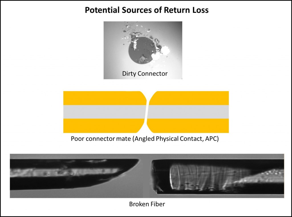
Dirty Connector
Some very simple faults in an optical network can cause high RL. A dirty connector is one such source. Even a tiny dust particle on a 5-micron single-mode core can end up blocking the optical signal, resulting in signal loss.
Broken Optical Fiber
A break in the optical fiber can also cause high RL. In some instances, the optical fiber may have a break but still guide light through. In this case, measuring insertion loss (IL) across the fiber will show low IL. This can disguise the extent of the problem, whereas a direct RL measurement would immediately highlight it. In addition, a crack in a fiber can have both low IL and low RL and be easily missed as a system problem. However, a sensitive RL measurement will show a reflection peak where there should be none, indicating a crack in the fiber that will likely lead to failure.
Poorly Mated Connector
If a connector is not fully seated, the resulting air gap between the connector end faces will cause high RL at that point. In this case, the IL may be low, and the signal fidelity could still be good. However, this is a concern because the loose connection could become misaligned or completely disconnected during service.
Creates Multipath Interference and Degrades Signal
Multiple high-reflection points within a network can cause the optical effect known as multipath interference. This interference can easily degrade the signal, especially in high-speed networks. In addition, many fiber optic transmission systems use lasers to transmit signals over optical fiber. High RL can cause undesirable feedback into the laser cavity, which can also degrade the signal.
Methods for Measuring Return Loss
Three established reflectometry techniques measure RL as a function of location along an optical fiber assembly or network: optical time domain reflectometry (OTDR), optical low coherence reflectometry (OLCR), and optical frequency domain reflectometry (OFDR). These methods trade off range, resolution, speed, sensitivity, and accuracy. Typically, low-coherence techniques are used for sub-millimeter-resolution measurements over a limited range (< 5 m). OTDR is typically used for long-range (several kilometers) measurements with low spatial resolution.
OFDR by Luna
OFDR, the technology used in Luna’s OBR product line, is ideal for measurements from the component level to short networks (up to 2 km). OFDR produces measurements with spatial resolutions as fine as 10 microns over 30 m or a few mm over 2 km. This high-resolution measurement over intermediate lengths can provide significant advantages. For example, when an OBR is used to troubleshoot a network on a small aircraft, it can pinpoint the location of a fault so a technician knows which panel to open or which side of a connector the fault is on. OFDR's sensitivity also makes it possible to detect small RL events, such as cracks, that would be difficult to detect with other methods but could lead to in-service failures.
Luna’s current OFDR-based test portfolio also includes the LWA 7600 Series for high-resolution reflection and transmission measurements of optical components, modules, and networks.
For more information on how OBR reflectometers use OFDR technology to deliver ultra-high resolution of loss, as well as polarization, dispersion, and other optical measurements, explore the OBR 4600.
References
Soller, B.J. et al., "High-resolution fiber reflectometry for avionics applications," Avionics Fiber-Optics and Photonics, 2005 IEEE, pp.56,57, 20-22 Sept. 2005
Kreger, S.T. et al., “Return Loss Measurement in the Presence of Variable Insertion Loss Using Optical Frequency Domain Reflectometry,” NIST SPECIAL PUBLICATION SP, 2006, 1055, 18.
Gifford, D.K. et al., "Millimeter Resolution Optical Reflectometry Over Up to Two Kilometers of Fiber Length," Avionics, Fiber-Optics and Photonics Technology Conference, 2007 IEEE, pp.52,53, 2-5 Oct. 2007
Bos, J.J. et al., "Mode conditioner and portable high-resolution reflectometer for maintenance and diagnostics of single- and multi-mode avionic fiber networks," Avionics, Fiber-Optics and Photonics Technology Conference (AVFOP), 2011 IEEE, pp.69,70, 4-6 Oct. 2011